DESIGN SMARTER: Practical Tips for Design for Machining
- Zakaria EL MLILAH
- Oct 1, 2025
- 2 min read

Updated: Oct 17, 2025
When designing a part for machining, every decision you make has a significant impact on the final appearance and cost of the part. The geometry of your model can determine whether you’ll need a lathe, a milling machine, a 5-axis CNC, or even a 6-axis robotic system. Even small choices, such as whether to include a chamfer or keep a sharp corner, can affect both the budget and lead time.
Therefore, when designing a part to be machined, take into consideration a lot of parameters. In this blog, I’ve shared several tips to consider before starting your design.
What is Machining?
Before getting started, let’s define machining. It’s a subtractive manufacturing process, meaning material is removed from a raw workpiece to achieve the desired shape. The machine can be operated manually or controlled by a computer system — known as a CNC (Computer Numerical Control) machine.
A CNC machine follows a G-code, which is generated by CAD/CAM software (for example, Fusion 360). This code tells the machine how to move the cutting tool to produce the part accurately.
Design Tips for Machining
Know your machines

Before you sketch a single line, think about the tools that will cut it. Is your part going to be milled on a 3‑axis CNC, turned on a lathe or finished on a 5‑axis machining centre? Each machine type has its sweet spot. Deep pockets, tiny holes or bizarre angles might look cool, but if they require expensive 4th axis setups or custom tooling, you're adding cost and lead time.
Use standard tools and stock sizes
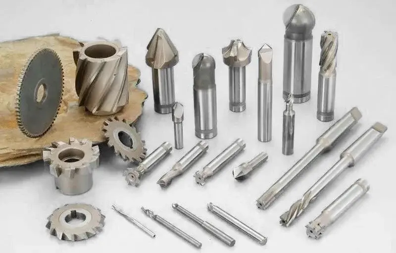
Machines love standardisation. Whenever you can, design features that can be cut with off‑the‑shelf end mills, drills and inserts. Holes should match common drill sizes. Slots and pockets should be wide enough to accept standard cutters. Start with stock dimensions that match readily available bar or plate sizes, you'll reduce waste and save your machinist from having to slab off excess material.
Be realistic with tolerances
It's tempting to call out ±0.01 mm everywhere, but not every surface needs that level of precision. Tight tolerances take more time and more passes. Identify the critical dimensions that affect fit or function and loosen up on the rest.
Simplify your geometry

Sharp inside corners and super‑deep cavities are a red flag for machinists because milling cutters are round and limited in length. Add radii to corners, break large parts into multiple pieces, and avoid features that require tools to reach down ten times their diameter. Simple shapes cut quickly; complex ones rack up machine hours.
Plan for fixturing and finishing

Ask yourself: how will this part be held during machining? Provide flat surfaces or holes that can be gripped or clamped. If the part needs threads or surface finishing, design those features with enough material for tapping or polishing later. Good fixturing surfaces often double as registration points in assembly.
These are just a few of the things to keep in mind when designing parts for machining. Working closely with the person who will actually make your part pays off every time. If you have a robotics or hardware project that needs to move smoothly from CAD to CAD, let's talk.
I love helping teams translate great ideas into real‑world hardware.


Comments